
Last updated: recently
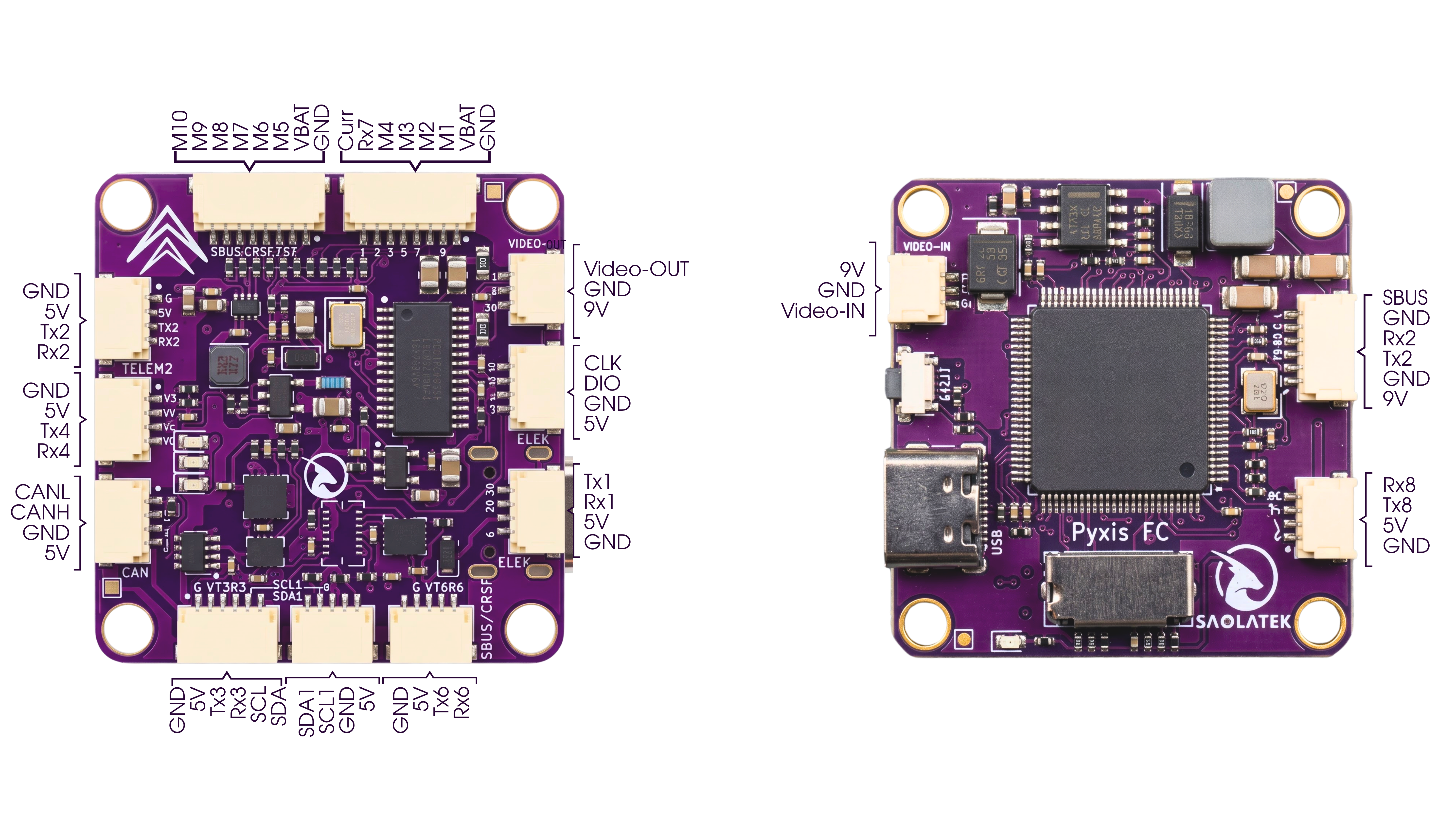
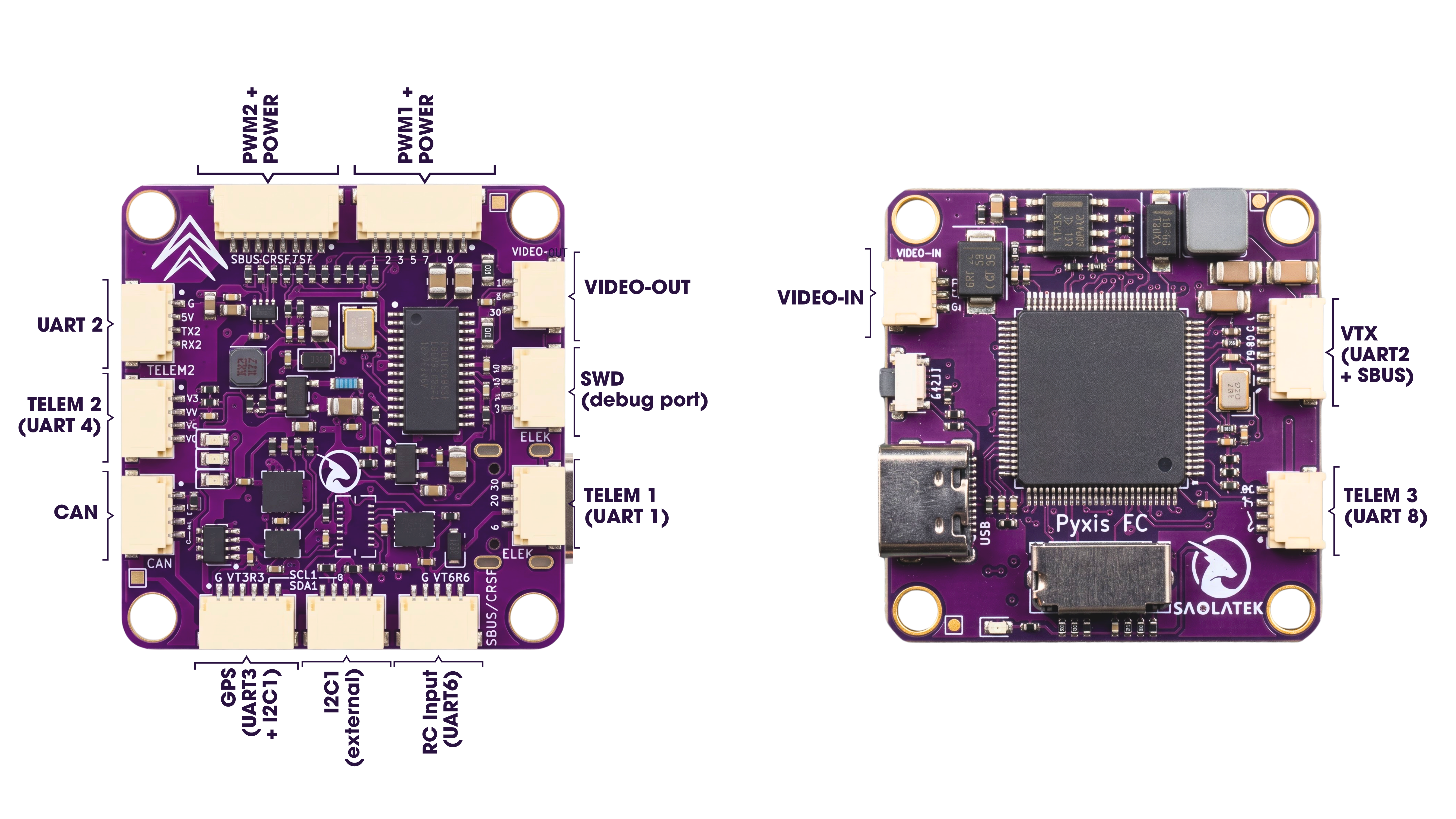
| UART1 | TELEM1 | TELEM1, 4-pin |
| UART2 | VTX | VTX, 6-pin — and the UART2 port, 4-pin (same signal) |
| UART3 | GPS | GPS, 6-pin |
| UART4 | TELEM2 | TELEM2, 4-pin |
| UART6 | RC Input | SBUS-CRSF, 4-pin |
| UART7 | ESC Telemetry (RX only) | PWM1, pin 7 |
| UART8 | TELEM3 | TELEM3, 4-pin |
| 1 | GND | GND | Black |
| 2 | 5V | +5V | Red |
| 3 | RX1 | 3.3V (logic) | Black |
| 4 | TX1 | 3.3V (logic) | Black |
| 1 | GND | GND | Black |
| 2 | 5V | +5V | Red |
| 3 | TX2 | 3.3V (logic) | Black |
| 4 | RX2 | 3.3V (logic) | Black |
⚠ This port carries the same UART2 signal as the VTX connector. Do not use both at the same time — this causes a bus conflict.
| 1 | 9V | +9V | Red |
| 2 | GND | GND | Black |
| 3 | TX2 | 3.3V (logic) | Black |
| 4 | RX2 | 3.3V (logic) | Black |
| 5 | GND | GND | Black |
| 6 | SBUS | 3.3V (logic) | Black |
⚠ Shares UART2 with the 4-pin UART2 port — use only one at a time. Pin 1 supplies 9V, not 5V.
| 1 | GND | GND | Black |
| 2 | 5V | +5V | Red |
| 3 | TX3 | 3.3V (logic) | Black |
| 4 | RX3 | 3.3V (logic) | Black |
| 5 | SCL1 | 3.3V (logic) | Black |
| 6 | SDA1 | 3.3V (logic) | Black |
| 1 | GND | GND | Black |
| 2 | 5V | +5V | Red |
| 3 | TX4 | 3.3V (logic) | Black |
| 4 | RX4 | 3.3V (logic) | Black |
| 1 | GND | GND | Black |
| 2 | 5V | +5V | Red |
| 3 | TX6 | 3.3V (logic) | Black |
| 4 | RX6 | 3.3V (logic) | Black |
| 1 | GND | GND | Black |
| 2 | 5V | +5V | Red |
| 3 | TX8 | 3.3V (logic) | Black |
| 4 | RX8 | 3.3V (logic) | Black |
| 1 | CANL | 3.3V | Black |
| 2 | CANH | 3.3V | Black |
| 3 | GND | GND | Black |
| 4 | 5V | +5V | Red |
| 1 | SDA1 | 3.3V (logic) | Black |
| 2 | SCL1 | 3.3V (logic) | Black |
| 3 | GND | GND | Black |
| 4 | 5V | +5V | Red |
| 1 | 9V | +9V | Red |
| 2 | GND | GND | Black |
| 3 | VIDEO IN | analog video | Black |
| 1 | 9V | +9V | Red |
| 2 | GND | GND | Black |
| 3 | VIDEO OUT | analog video | Black |
| 1 | 5V | +5V | Red |
| 2 | GND | GND | Black |
| 3 | SWDIO | 3.3V (logic) | Black |
| 4 | SWCLK | 3.3V (logic) | Black |
| 1 | GND | GND | Black |
| 2 | VBAT | 3S–6S | Red |
| 3 | M1 | 3.3V (logic) | Black |
| 4 | M2 | 3.3V (logic) | Black |
| 5 | M3 | 3.3V (logic) | Black |
| 6 | M4 | 3.3V (logic) | Black |
| 7 | RX7 (UART7, ESC Telemetry — RX only) | 3.3V (logic) | Black |
| 8 | Current Sense | 0–3.3V analog | Black |
⚠ Pin 7 (RX7 / UART7) is RX only — it receives ESC telemetry and cannot transmit.
| 1 | GND | GND | Black |
| 2 | VBAT | 3S–6S | Red |
| 3 | M5 | 3.3V (logic) | Black |
| 4 | M6 | 3.3V (logic) | Black |
| 5 | M7 | 3.3V (logic) | Black |
| 6 | M8 | 3.3V (logic) | Black |
| 7 | M9 | 3.3V (logic) | Black |
| 8 | M10 | 3.3V (logic) | Black |
⚠ Pin 2 on both connectors is raw battery voltage (VBAT), NOT a regulated 5V rail.
| 1 | M1–M4 | TIM1 |
| 2 | M5–M6 | TIM3 |
| 3 | M7–M10 | TIM4 |
| BATT_MONITOR | 4 |
| BATT_VOLT_MULT | 11.0 |
Verify BATT_VOLT_MULT against a multimeter and fine-tune if needed. BATT_AMP_PERVLT depends on your ESC or power module, not on the flight controller.
RC Input Setup
OSD
Power Warning
External Compass